
Mike-O-Wave
Built by Mike Walters, 2008
Back to
Mystery Circuits Projects
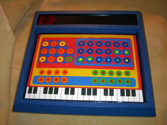
I finished building the Mike-o-Wave at the end of 2008. Early in the year, I found a really cool blue box at work, and it turned out to be a Heathkit Experimenter my boss built when he was in high school. I found one just like it on ebay, and planned to make something fun out of it. The brain of a Yamaha PSS-140 made its way inside, and is now controlled by laminated paper and logic switches. The musical advantages of having real, albeit small, keys and rubber buttons on an instrument have devolved to tiny clicks on an awkwardly small, flat, shiny surface. Yes, it's polyphonic!
Each switch, including the entire keyboard, was removed from the Yamaha circuit board, then remapped under the Mike-o-Wave panel with copper tape. The original idea was to build a membrane switch panel with 3 layers, but that wasn't very practical. So I bought 100 tactile switches from China (off ebay), and soldered those onto the tape. They work very well!
The control panel was made from construction paper, and labels from an office supply store (dots, donut supports, and price tags). I drew up a little keyboard, printed it, and arranged everything. It really looks like a Speak n' Spell, doesn't it? The collage was photocopied, then laminated.
There are 18 total circuit modifications on the Yamaha. The first 8 are the popular FM mod. I don't know who originally discovered this modification, but it's been around the internet a few years. The mod is to install on/off switches between data lines feeding the FM chip. This makes the audio glitch in fun ways. The 10 other mods are simple on/off circuit bends I found.
All of the mods are turned on and off using logic switches. There are LED momentary switches under the paper, and each switch is wired to a 4027 flip-flop IC. Pressing the switch sends a momentary pulse to the 4027's input, and its outputs flip-flop between two different states, high and low.
One of those outputs is wired to a 4066 switching IC. The data line/FM chip connections, and the circuit bends are switched on and off via the 4066 chips.
The outputs of the 4027's are handled differently between the FM mods and the circuit bends. Since the FM mods activate when the data line/FM chips are open, they rely on output one being held low to gate. When the Mike-o-Wave is turned on, a charge is automatically sent to those 4066's. When the button is pressed and the 4027 flip-flops, the connection is broken. This turns on the mod. That also means the second output goes high, and that latches the LED inside the button until the button is pressed again.
The circuit bends work opposite. Those mods are active when the 4027's second output is high, closing the circuit. When the Mike-o-Wave is turned on, and the 4027's are on output one (this means the gate is inactive). When the buttons are pressed, and output two goes high, the 4066 closes the connection, and the LED goes on in parallel.
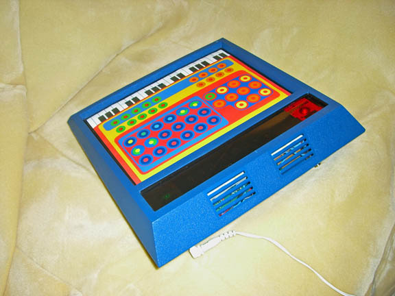
The power switch for the Mike-o-Wave is a red plexiglass square. A mechanical push on-push off switch sends power from the DC input on the back. A big red jewel lights up. You can see the original PCB graphics from the Heathkit inside the window.
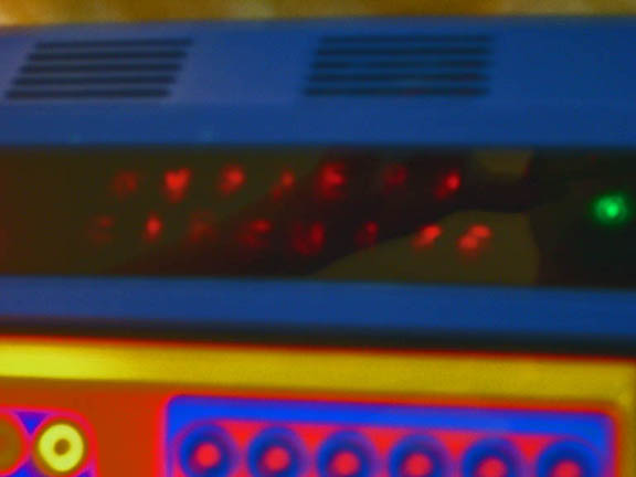
Finally, I made a cheesy little "Mystery Circuits" LED display. Under the black transparent plexiglass, there are 15 red LEDs. I spelled "MYSTERY CIRCUITS" over each LED, and put a small acrylic hemisphere on top of each letter to magnify it. The top and bottom LED on each row is wired parallel to eight steps of a 4016 decade counter. This is clocked by a 555 timer running at 7Hz. On the Yamaha, I found a point on the circuit that changed between 0 and 3v in time to the music, but at seemingly random intervals. I sent this point to gate a transistor feeding the control voltage input of the 555. The audio from the Mike-o-Wave goes into the input of the transistor. This causes the "MYSTERY CIRCUITS" sequence to change from normal 7Hz operation to bugging out. Parallel to the CV source feeding the 555, is a green LED lighting up "Mike O' Wave" beside the sequence. There's a little plastic piggy by the green LED. You can also see the original Heathkit circuit board graphic when this lights up.
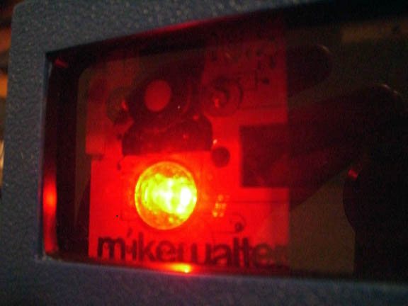
Red Jewel, mechanical switch,
PCB graphics and Mike Walters
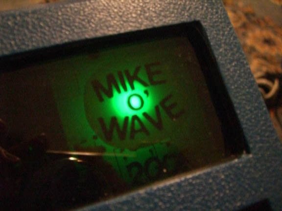
Mike O'Wave 2008 and a piggy
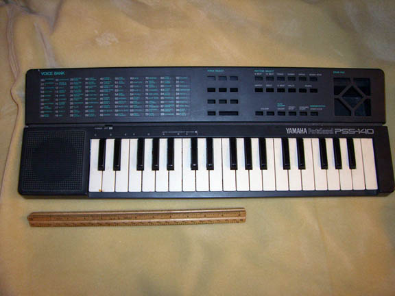
The original Yamaha
keyboard