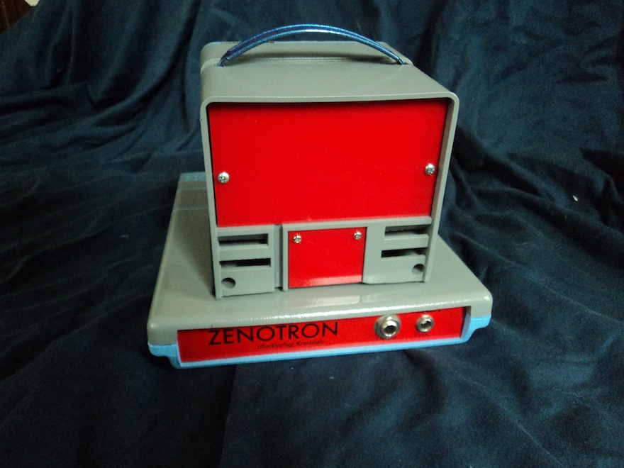
ZENOTRON
Built by Mike Walters
Chapel Hill, NC 2014
mike@mysterycircuits.com
A couple of months after I moved back to NC from NY, my friend Zeno and his family moved back to NY from NC. Zeno gave me some keyboards, and in return I would build him something. Fast forward a couple of years, I built him the Zenotron!
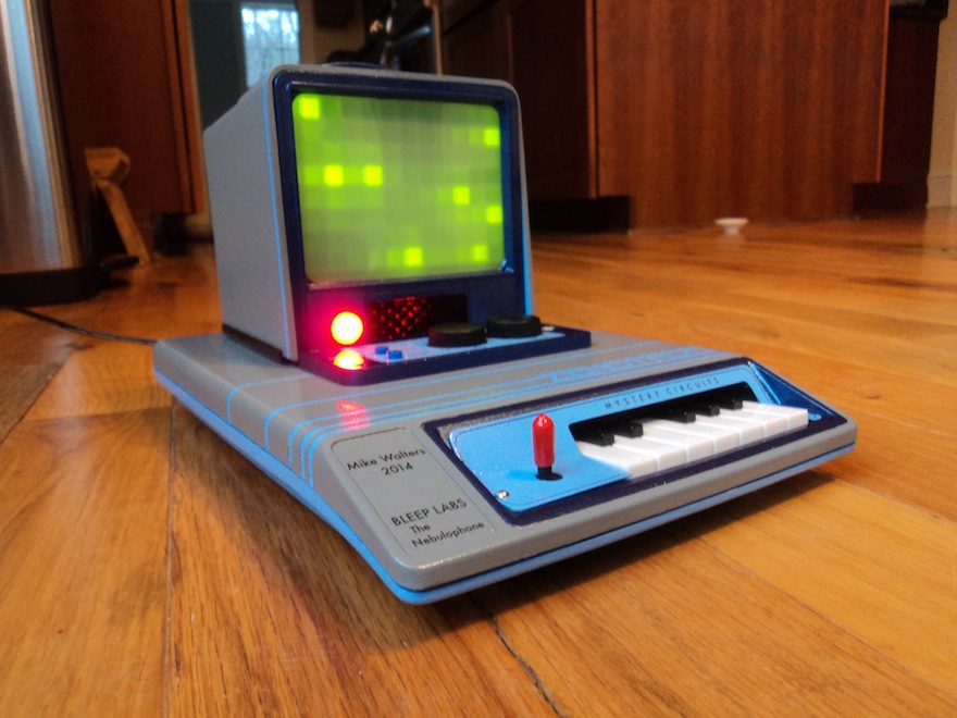
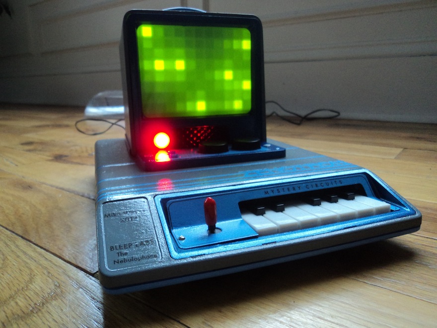
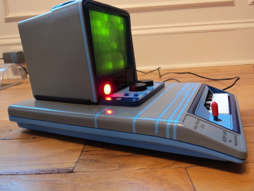
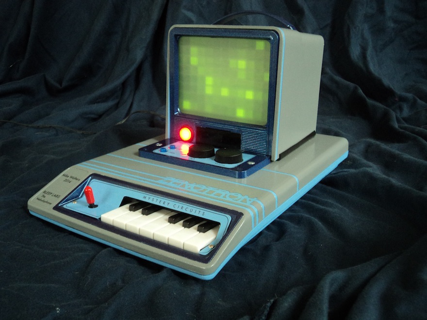
The case was made from an old modem, the monitor was a small filmstrip viewer I cut in half. Behind the translucent screen is a cut down pipette box. I installed 88 LEDs where the pipettes normally go (perfect fit). The miniature keyboard comes off of an old toy, and I rebuilt the key contacts from little surface mount tactile switches.
The sounds on the Zenotron come from a modified BleepLabs Nebulophone kit. A 2-Axis Parallax joystick controls the waveform and arpeggio rate of the Nebulophone. There are only 10 notes on the Nebulophone circuit, so the A# and B of the keyboard are wired parallel to the C and C#.
Audio from the Nebulophone is fed to the clock input of a 4017 decade counter, which varies the sequence speed according to the Nebulophone's audio. Each step turns on two transistors that light an array of 4 to 5 green LEDs. All of the LEDs are wired randomly, though I tried to make sure the spread around the pipette box was even. The LEDs are wired to a DB25 connector inside the Zenotron.
For the volume pot, I just replaced the feedback resistor in the last opamp stage of the Nebulophone's output. The LFO pot is wired the same as on the Nebulophone, but it has an off switch when turned all the way down. If the switch is off, the LFO seems to change according to the joystick. The LFO controls the Nebulophone's filter, which uses an optocoupler.
The color scheme was very much subconsciously inspired by the Kaypro II and the Commodore SX-64
Please enjoy the video and some pictures.
In the kitchen. The big red light is the latching power switch
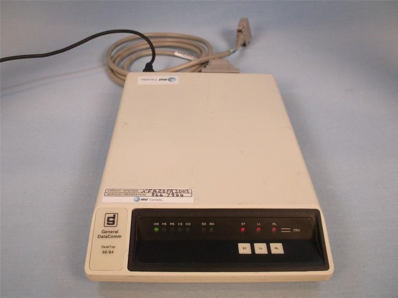
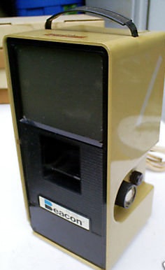
I forgot to take before shots of the modem and filmstrip viewer, but I found these photos of identical units on old auction sites:
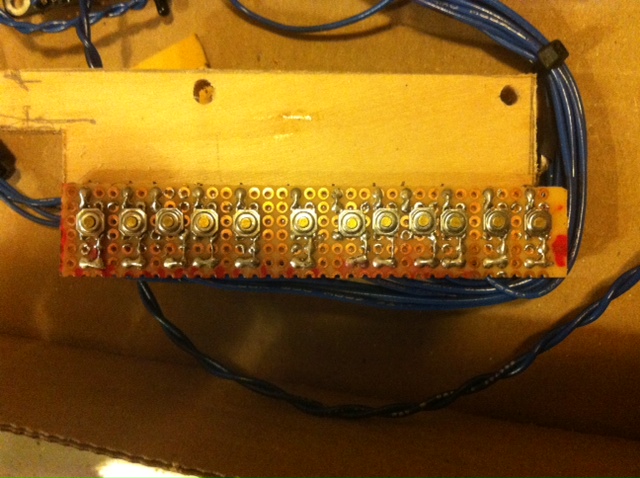
Here's the key contact board with the tactile switches. It was tricky lining them up to the keyboard,
and compromising their positions because of the solder pads. But it works! And clicks like a mouse!
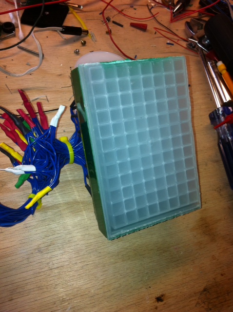
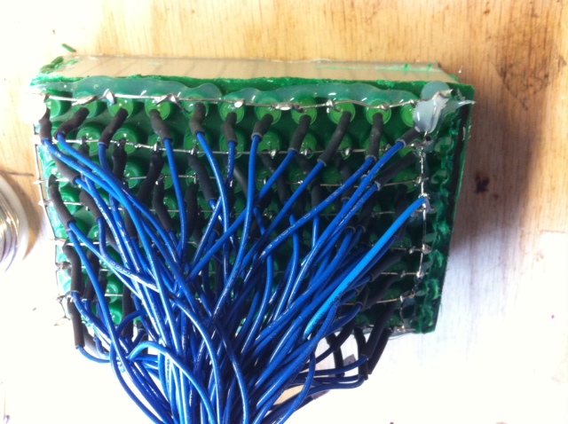
Pipette box was cut down slightly to fit inside the screen. 88 LEDs are wired to the pipette holes.
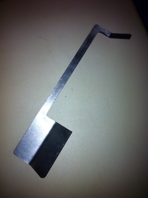
Face plate cut out with CNC, bent with bending brake
There's a little light diffuser for the arpeggio rate LED beside the power switch. The diffuser was made for a ceiling light.
The small panel under the monitor that holds the two buttons and two pots comes from the bottom part of the filmstrip viewer
The back pieces were remade in red plexiglass with my CNC. But the bottom panel is actually thin white plexiglass painted red to match.
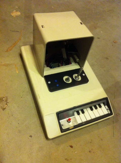
Before the paint...
A couple of months after I moved back to NC from NY, my friend Zeno and his family moved back to NY from NC. Zeno gave me some keyboards, and in return I would build him something. Fast forward a couple of years, I built him the Zenotron!
The case was made from an old modem, the monitor was a small filmstrip viewer I cut in half. Behind the translucent screen is a cut down pipette box. I installed 88 LEDs where the pipettes normally go (perfect fit). The miniature keyboard comes off of an old toy, and I rebuilt the key contacts from little surface mount tactile switches.
The sounds on the Zenotron come from a modified BleepLabs Nebulophone kit. A 2-Axis Parallax joystick controls the waveform and arpeggio rate of the Nebulophone. There are only 10 notes on the Nebulophone circuit, so the A# and B of the keyboard are wired parallel to the C and C#.
Audio from the Nebulophone is fed to the clock input of a 4017 decade counter, which varies the sequence speed according to the Nebulophone's audio. Each step turns on two transistors that light an array of 4 to 5 green LEDs. All of the LEDs are wired randomly, though I tried to make sure the spread around the pipette box was even. The LEDs are wired to a DB25 connector inside the Zenotron.
For the volume pot, I just replaced the feedback resistor in the last opamp stage of the Nebulophone's output. The LFO pot is wired the same as on the Nebulophone, but it has an off switch when turned all the way down. If the switch is off, the LFO seems to change according to the joystick. The LFO controls the Nebulophone's filter, which uses an optocoupler.
The color scheme was very much subconsciously inspired by the Kaypro II and the Commodore SX-64
Please enjoy the video and some pictures.
In the kitchen. The big red light is the latching power switch
I forgot to take before shots of the modem and filmstrip viewer, but I found these photos of identical units on old auction sites:
Here's the key contact board with the tactile switches. It was tricky lining them up to the keyboard,
and compromising their positions because of the solder pads. But it works! And clicks like a mouse!
Pipette box was cut down slightly to fit inside the screen. 88 LEDs are wired to the pipette holes.
Face plate cut out with CNC, bent with bending brake
There's a little light diffuser for the arpeggio rate LED beside the power switch. The diffuser was made for a ceiling light.
The small panel under the monitor that holds the two buttons and two pots comes from the bottom part of the filmstrip viewer
The back pieces were remade in red plexiglass with my CNC. But the bottom panel is actually thin white plexiglass painted red to match.
Before the paint...