


Mystery Circuits, LLC

By Mike Walters - Chapel Hill, North Carolina


The Drumssette
Built by Mike Walters
New York, NY, 2010
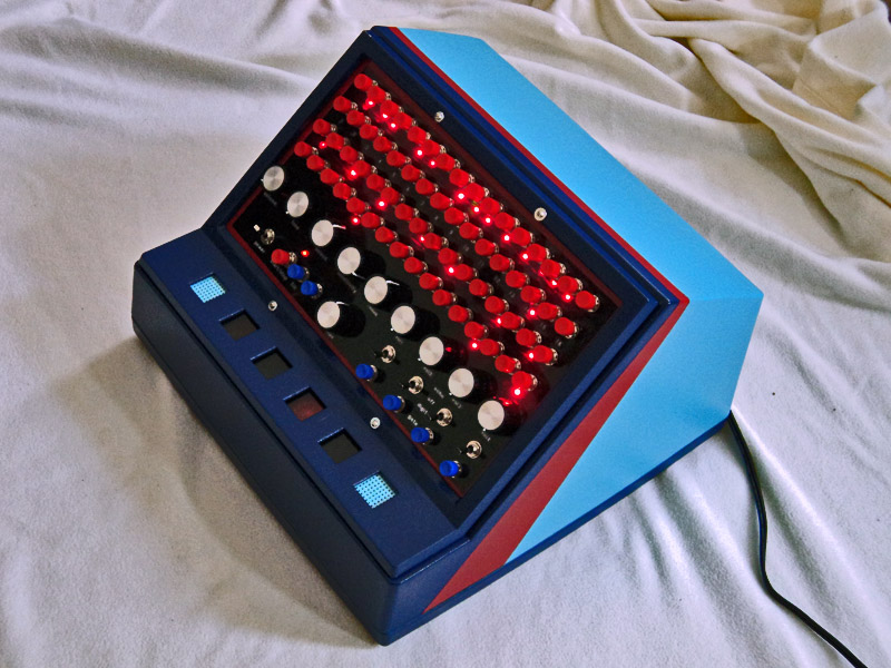
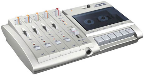
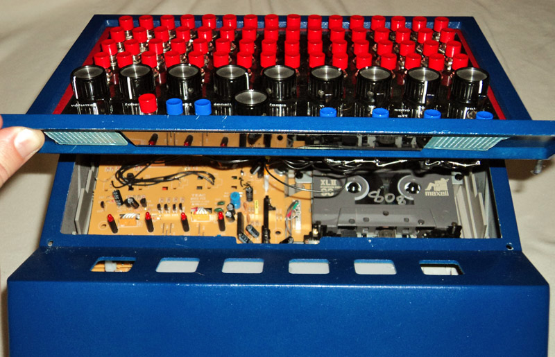
The Drumssette is a programmable drum machine I built using a Tascam four track cassette recorder. The sounds of the drums come right off the prerecorded cassette tape, and those sounds also clock the sixteen step sequencer inside. As the cassette plays, rhythms can be mapped out on the switch interface. This is how it works...
Each of the four tracks on the cassette tape contain a single, repeating drum sound. Track one has high hat, track two cymbal, bass drum on track three, and the last track has snare. These drums are synchronized with each other, and each track is isolated from the next.
There's a four position rotary switch on the front panel of the Drumssette. This switch routes a parallel audio signal (this doesn't go to the output) from one of the four tracks through the Tascam's headphone amp circuit, through a delay stage, another amplifier, and finally to the clock input of the 16 step sequencer. The selected audio signal determines the frequency of the sequencer, and causes it to step.
As the sequencer steps, each output is sent to a bank of AND gates. On the front panel of the Drumssette are 64 push on/push off (mechanical) switches in four rows of sixteen. These are wired with a common connection to the 9v supply bus, with individual outputs going to the other inputs of the AND gates. There are 64 AND gates total. If a switch is on, AND the sequence step is on, the output of the gate is 1. This will momentarily unmute that track's audio to the output, through a "Wired-OR" configuration using diodes.
Since the trigger for the sequencer clock is audio used in parallel with the actual sounds of the instrument, the triggered audio from each track might lose a bit of its attack when it gets to the output, especially if the sound has a slower attack. To solve this, I built a delay stage before the parallel audio gets to the sequencer. This audio does not go to the output of the Drumssette. Using a PT2399 digital delay chip, the parallel audio signal is treated with a simple, adjustable delay, with no feedback (repeat stages) and a clean output. Delaying the audio signal before it becomes the clock signal allows the the operator to apply an adjustable delay parameter to the sequencer, which allows the gating to scoot over and focus on the next drum sound on the tape before the loss of attack. This happens because the audio on the cassette is time constant, and the delayed signal is variable. The momentary unmuting (gating) is dictated by the delay signal. You can also focus between sounds, to create double time beats.
There are two methods of gating the cassette's audio, selectable by toggle switches on the front panel. These switches route the audio of each track through either a 4066 switch for a digital on/off, or through an optocoupler stage for an analog on/off. The analog method gives the drum sounds echo.
In position one (the digital method), the audio of each track is routed through a 4066 switching IC. When the gate is high, the 4066 switches on to pass the audio. A low gate opens the switch, and doesn't route the audio to the output. The gated sounds are either on or off, according to the state of the 4066.
The analog method is different. When this mode is selected, the audio from the tape is passed through a photo-resistive circuit using optocouplers. Optocouplers are little capsules with photoresistors and LEDs inside. Photoresitors become less resistive with more light, so when the LED is on, they suddenly drop to a few ohms. When the LED is off, they go back to a couple mega ohms. The photo resistive material, Cadmium Sulfide, retains some light energy between stages. So, as opposed to a switch, the optocoupler fades in and out the signal much slower. This gives the sounds a synchronized echo (you can hear the next four or so drum steps on the tape as it fades out). This mode actually uses two optocouplers, and an inverter. These are wired in parallel to pass the signal when triggered, and then ground the signal when the gate is low. When the gate is low, the inverter changes the logic, switching optocoupler LED 1 on. When the gate is high, LED 1 turns off, and optocoupler LED 2 turns on. So, the signal is always passed or grounded in this configuration. If the signal is not grounded, there will be a little bit of signal bleeding to the output.
Underneath those analog/digital toggle switches are manual triggers. These are momentary, and simply send voltage to the gate to turn the cassette track on. This is done after the digital/analog trigger selection, so the drums will trigger according to those positions. If analog triggering is selected, you can manually trigger the drums with echo. The drums still loop in real time from the cassette, so manual triggering always does so in perfect time with the sequenced drums.
The "Fill" switch acts the same way, but manually triggers all four tracks at the same time to provide a campy, momentary passage during the rhythmic generation.
The sequencer provides 16 steps using a single 4017 decade counter, a 4027 flip-flop, and four 4081 AND chips. The clock for the sequencer comes from one of the audio tracks on the cassette. This is how it works:
First, I had to get a good clock signal from the audio tracks. The signal had to be around headphone level, and then amped some more. I did some rewiring on the Tascam to use the built in headphone amplifier, and that gets the feed from the 4 position rotary switch. This signal is then run through a non-inverting op amp, and then through a Darlington transistor stage with a pull down resistor. This feeds the clock input of the 4017, as 0's and 1's at the rate of the repeating drum sound.
The 4017 gives 10 output steps at the frequency of the clock input. You can easily lower the amount of steps by sending the next highest step to the reset pin. So, if you want 8 steps, you would send step 9 to the reset. To get 16 steps, I had to add some additional circuitry.
On the 4017, I sent step 9 to the reset to get 8 steps. Parallel to step 9 goes to the input of a 4027 flip-flop. The flip flop changes states between output 1 and output 2 whenever the input goes high.
Next is an array of AND gates. Sixteen total (there are four gates per chip). Steps 1-8 of the 4017 go to input 1 of each AND gate (coupled so step 1 goes to AND gate 1 and 9, step 2 goes to AND gate 2 and 10, etc...). The outputs of the 4027 go to the other inputs. Output 1 goes to AND gates 1-8, and Output 2 goes to AND gates 9-16.
The outputs of the AND gates then trigger the 16 green LEDs as a repetitive sequence, and feed the drum triggering AND gates.
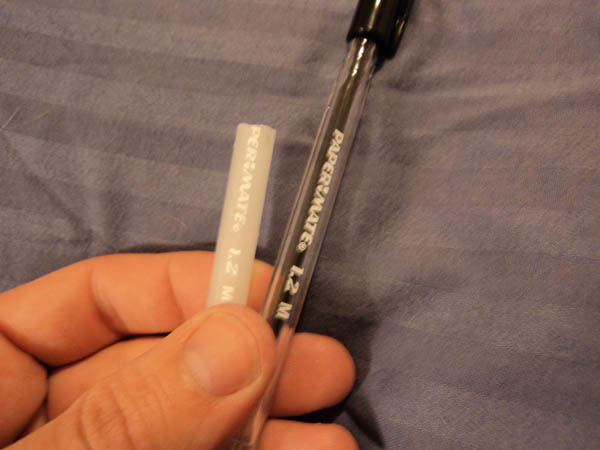
The 16 green LEDs are housed inside of pens. Standard Papermate pens I bought from Duane Reade. I cut the pens down to about 3.5", and the LEDs serendipitously fit inside. To achieve better light transmission through the plastic, I dipped each pen carcass in acetone for about 20 seconds, and rinsed. Now instead of clear, the pens are a translucent, milky white. When the green LED turns on, the broken pen shell becomes a mini light saber illuminating the backs of the four switches for a tiny second.
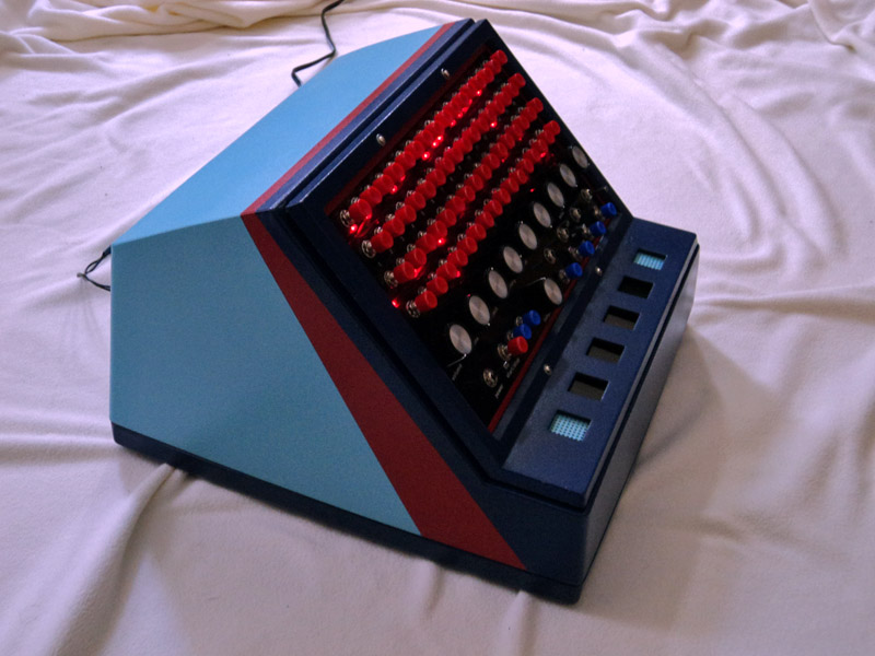
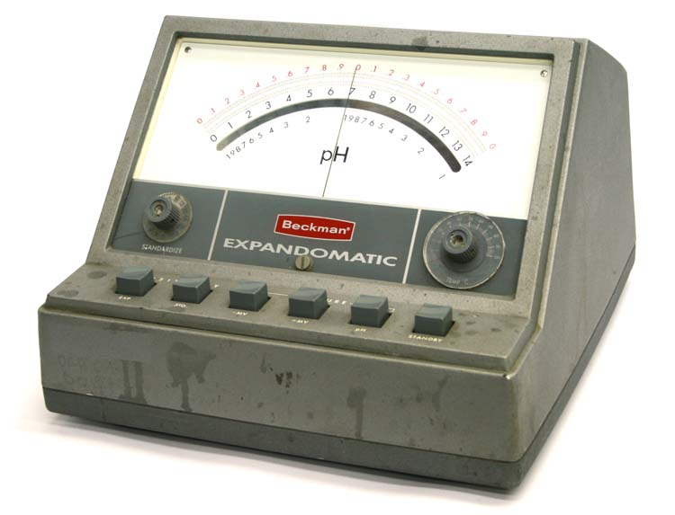
When I build an instrument using a repurposed case, I usually have the case first. The case normally sits around my home for years or months before I do anything with it. The Drumssette was different. I had the idea, I bought a four track off ebay (contained a cassette with some strange DIY christian folk with creepy harmonies and acoustic guitar), but I didn't have the right case at hand, or in mind. The case had to be large enough to house the circuits and the tape machine, and it also had to open for access to the play, rewind, and stop controls. Finally on ebay, I found a Beckman analog pH Meter with a giant needle. The seller gave me the dimensions, and it could accommodate the width of the Tascam. I bought it for $10. When I took it apart, I was very pleased to discover the top could be removed, and could be fashioned into a door to access the controls of the tape player.
Over the months, I drew up a design for the user interface. I didn't have all the electronics designed, so I had to add new controls as new circuits were made. Once the design was complete, I drew up everything in TurboCAD according to the exact measurements. I used transparent black Plexiglass to hold the knobs and switches. All the LEDs are underneath the surface and are only visible when activated. I've always liked that effect. I took my CAD design to Canal Plastics in Chinatown, and they laser cut the Plexiglass. I highly recommend this place if you're in New York!
If you've seen my project, The Melloman, you'll see a resemblance in the color scheme. The Drumssette is the sequel to The Melloman five years later. I did the painting at my work. They were very generous to allow me to spray paint in the office on weekends. Sorry for the Monday morning headaches.
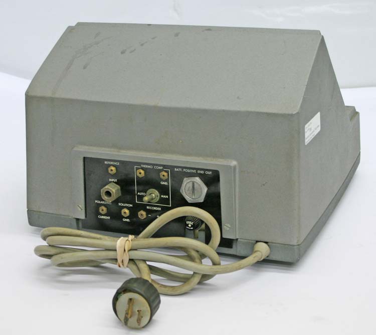
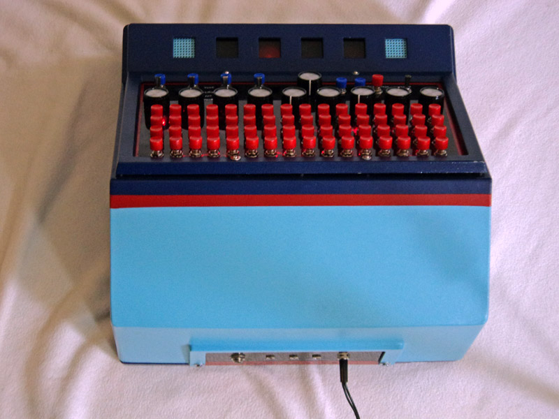
I used the back control plate of the Beckman pH meter as a template for the Drumssette's I/O interface. I also had this piece laser cut in black transparent Plexiglass from Canal Plastics. The back of the Drumssette has the main audio out on a 1/4" jack, a 12v DC input, a 3.5mm clock output, and two 3.5mm audio inputs that bypass the cassette audio, and clocking. I've noticed, increasingly, a lack of enthusiasm for portable magnetic tape media in North America. Come to find out, more and more people are focusing their attention on solutions that accommodate an entire musical library on a decidedly digital method of both playback and storage. Say you've moved on, and you embrace the digital lifestyle. You too can participate in the Drumssette's method of analog audio gating by plugging the headphone outputs of two digital media players (or any kind of audio) directly into the back of the instrument. The 3.5" jacks are switchable, and automatically bypass the audio of the cassette's four tracks. Jack one bypasses tracks 1 and 2, jack two bypasses 3 and 4. The audio is bypassed before the clock stage, so now the Drumssette's sequence frequency can be dictated by one of the external audio sources. You can also play the tape and clock the sequencer, but bypass only two tracks. For example, you can sequence the bass drum and snare on tracks 3 & 4 from the cassette tape, then send an alternate source to 1 & 2. This is good for those people who haven't gone fully digital, but only 50% digital. The sequencer's clock signal is fed parallel to the Clock Out on the Drumssette, so you can sync up the Drumssette to other instruments.
Drumssette Functions
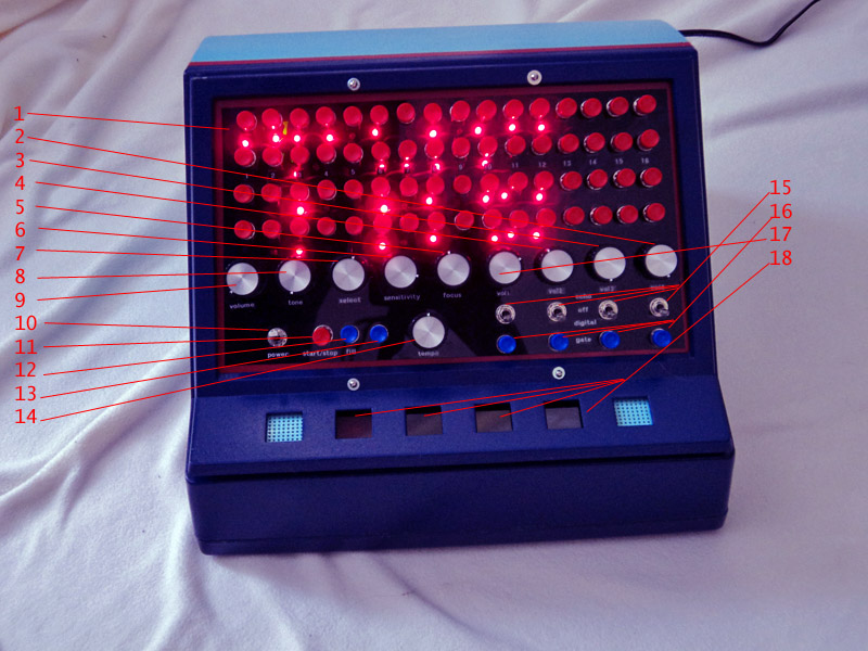
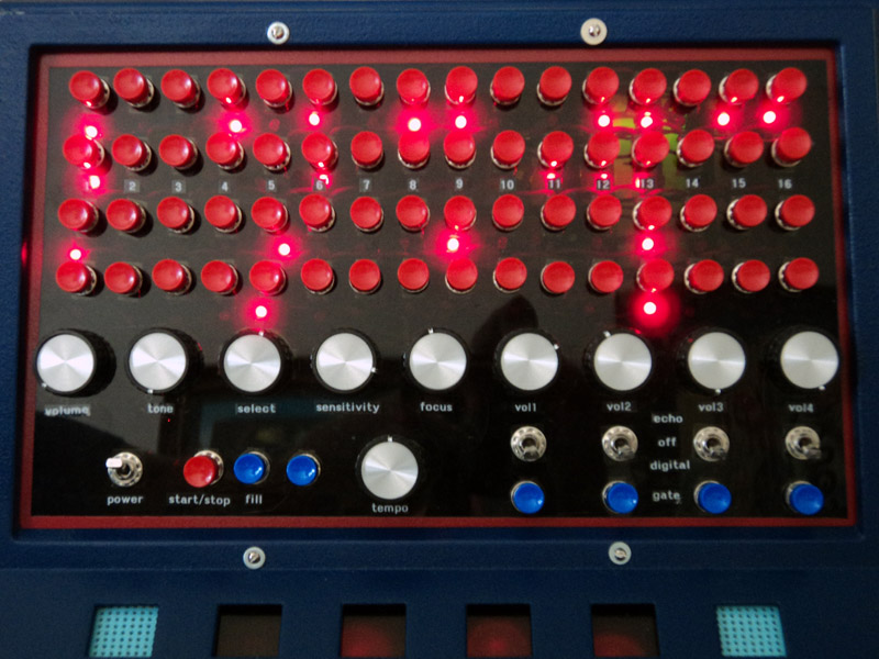
1) Sixty Four mechanical push on/push off switches. When on, an LED attached to the bottom lights up. These map the drum beats.
2) Volume control for drum track 4
3) Volume control for drum track 3
4) Volume control for drum track 2
5) "Focus" changes delay rate of PT2399 feeding sequencer. Allows you to scoot over gate to compensate for attack loss, or make double time/warped beats
6) "Sensitivity" attenuates analog signal amplitude that feeds sequencer clock, before it goes through delay stage
7) "Select" is a four position rotary switch that selects one of the four tracks to feed the sequencer clock
8) "Tone" is a passive low pass filter
9) Master volume control
10) Power switch
11) Start/Stop activates the sequencer, and starts the rhythm
12) "Fill" is momentary drum fill. When pressed, it gates all four tracks at the same time. Basically, this unmutes everything
13) "Reset" resets the sequence
14) Tempo control adjusts pulse width of PWM circuit powering motor. This slows down/speeds the motor, which changes tempo and pitch of drums
15) 3-way toggle switches determine method of gating. Up is "Echo" (analog gating), middle position is off, down is digital on/off gating. Each track
is controlled discretely.
16) Manual trigger buttons momentarily gate the individual tracks for as long as buttons are pressed down. These will trigger according to "echo/digital"
switch position
17) Volume control for drum track 2
18) LEDs give parallel feedback for digital gating status per track. LEDs are diffused through two layers of frosted plastic material, and under tinted
Plexiglass
Making Tapes
The type of Tascam four track I used is indeed a recorder, but ironically it doesn't work well making tapes for the Drumssette. That's why I didn't include any recording inputs on the instrument. This Tascam is a four track in its most simple form, and it doesn't allow multi-tracking. You can only record one track at a time. To make tapes properly, all the drum tracks have to be in perfect sync, and completely isolated from each other. This is where good friends come in handy. Thanks Ben and Lindsay for letting me borrow your nice, multitracking Yamaha 4 track for so long. Your heart is true, you're a pal and a confidant.
I built the tracks using the recording program Logic on my computer. I created four drum sounds, and repeated them on a loop synced up to each other. My audio interface has 4 outputs, so I could discretely run each track to separate inputs of the mulitracker to record the sounds on tape. In the end, the tape is pretty obnoxious, containing sixteenth beats of each sound repeating. Pressing the "Fill" button on the Drumssette is what the tape sounds like totally open.
The tapes I used are 90 minute Type II's . I didn't even try to use looping tapes. First, I couldn't get the looping TDK tapes to separate tracks back when I built the Melloman, and a drum beat would require a very precise loop to keep the rhythm moving in time. So for songs over 90 minutes, I would recommend a longer tape.
Sound Samples and Video Clips
Audio
Recorded with 808 style drum cassette
1) Sample of the Drumssette and some of its functions, including Digital vs Analog gating, drum fills, and manual triggering. Focus adjustment starts around 33 seconds.
2) Sample of flipping the cassette over in the Drumssette. This makes the drums play backwards! You can map out the beats in forward time like normal, but the sounds are
reversed. When the tape is flipped, all the functions will have to flip too. What controlled the hi-hats normally now controls the snare, etc. Also, the clock's track selection
might need to be changed.
3) Sample of the Drumssette with an ipod connected to tracks 1 and 2. Plugging into this jack will disable tracks one and two on the cassette, replacing it with the source
connected (the ipod). The bass and snare are from the cassette tape, and tracks 1 and 2 are gated on and off according to the switch states on the front panel. This is gating
Jean Michel Jarre's Oxygene.
4) Sample of the Drumssette with a Yamaha CS01 going into track 1, and record player going into track 2, bypassing cassette on those tracks. Bass and snare come from
cassette. The rhythmic keyboard phrasing is completely from the Drumssette. I was just holding notes down on the keyboard. Same thing with the record on the
other track. See the youtube video!
Intro Video
Video doing the same thing I described in audio sample 4.
Running Polymoog into Drumssette. Vox Humana sound routed to external input 1, bypassing cassette tracks 1 (and 2). Drumssette chops the Polymoog's
audio according to the states of mapping switches.
Different sounds. The first part of the video features sounds I recorded from the Minimoog. I made the hi-hat and snare from different envelopes of white noise. The kick
comes from a fast, oscillating filter sweep using a low cut off frequency. The second track is an oscillating filter sweep spanning the entire measure (I cheated by time-stretching
in Logic). I also manually gate this track during the sequence. The second part of the video shows CR-78 samples, and the third video shows acoustic drum sounds.
4) Flipping the tape over to sequence backwards drum sounds on the Drumssette
I started building the Drumssette in October 2009, and got things mostly finished in May of 2010. Still there was more work, and there's even a few more things to do
as of July 2010. I still want to make more tapes, and make more improvements on it. For example, I still have to modify the power supply to provide an isolated lead
to the cassette motor. The tempo control works, if you like to hear a 100Hz pulse wave on the audio output. I can solve it this way, but I still have to do it. I'd also
like to create a snazzy logo. The other thing on the to do list is to make the LEDs for the sequencer and the gate status squares on the front brighter. The first square isn't
as bright as the other squares, so I need to look into that. Anyway, here are some pictures I took documenting the build over those months. This was all built on my
living room floor in Manhattan.


