Mystery Circuits, LLC

By Mike Walters - Chapel Hill, North Carolina


New Melloman
Built by Mike Walters 2012-2013
Chapel Hill, NC
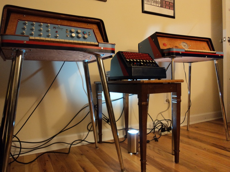
This is the new Melloman, built eight years after its predecessor. It was commissioned by Justin Vernon (Bon Iver, Volcano Choir), and took me a little over a year to complete.
Like the original Melloman, this is my DIY design of the classic Mellotron.
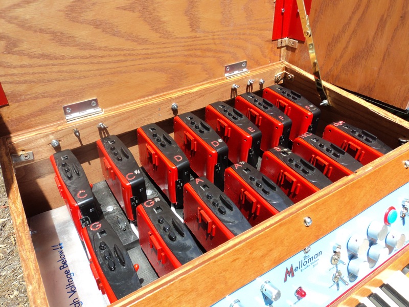
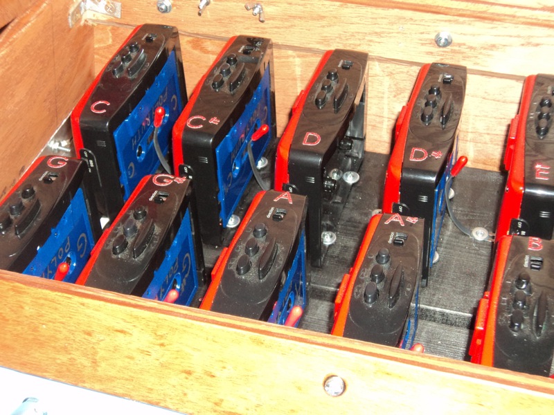
There are 14 Walkmans inside the Melloman, running tapes of continuous notes. Each tape has two octaves of a looping sound, and those sounds are routed to the output when a key is pressed on the keyboard.
The new Melloman is a complete redesign of the original Melloman I built in 2005.

The original Melloman used only transistors to pass the sounds from each cassette to the output. When I built that one, I experimented with photo resistive opto-couplers, but had problems with the signals continuing to bleed through after the note was off. I thought of a solution a few years later, and implemented that in this new design.
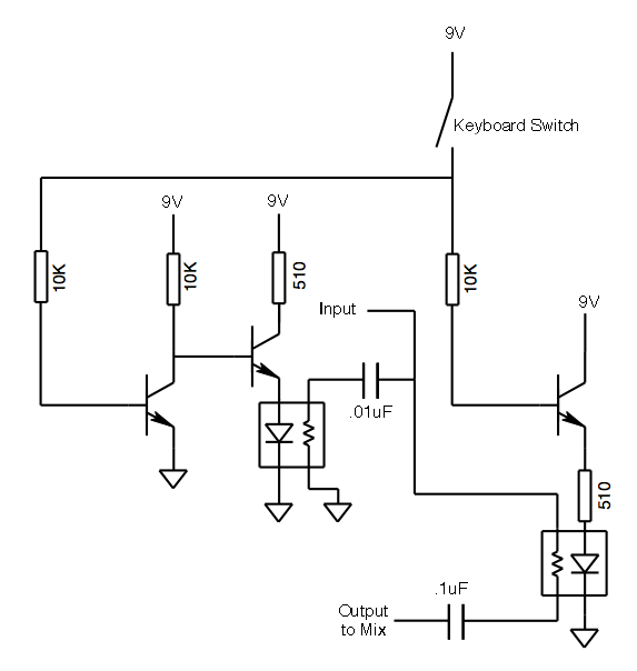
The new Melloman now uses opto-couplers to gate the notes. In order to remove the transient bleeding after the note is let go, a parallel opto-coupler grounds the note. So each channel uses two opto-couplers, and three transistors to switch them. When the note is pressed, one of the opto-couplers is energized, passing the signal to the output mix. When the note is let go, that opto-coupler turns off, and the other opto-coupler is energized. This sends the signal to ground to mute the note.
Using opto-couplers, the gating sounds smooth. Just using transistors on the original Melloman, the gating was a bit clicky.
Here's the schematic for gating notes. It's simple:
On the new Melloman, each tape player can be tuned individually on the control panel (by the way, this new version uses Memorex portable tape players instead of Sony Walkmans. But I still refer to the tape players as Walkmans). Each player has a voltage divider trim pot inside to govern the tape speed. On the panel, there are 13 pots wired in parallel to each trim pot. But I added the 3v rail to each, so they can be tuned up as well as down. Also, these tape players have Auto-Reverse, so you don't have to rewind when the tape is over. I've never actually used looping tapes. I tried using 3 minute looping tapes years ago on the original Melloman, but there was too much bleeding between tracks.
The tape set I included with the new Melloman is called "Poly-Ruth". The first octave is my wife Ruth singing each note layered three times, the second octave is from my Polymoog doing the famous Vox Humana preset.
Like the original Melloman, each tape uses the Left and Right tracks to provide two octaves. The left and right aren't actually routed as stereo, they are mixed together with all of the other tape tracks to produce a mono signal. When tuning on the control panel, each pot will tune both octaves. But the Hi-C note has its own tuning pot.
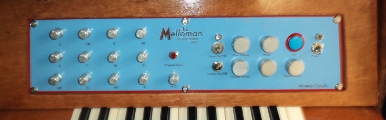
There is a little red light under the Melloman logo that will flash when the tapes are about to flip sides. Here's why: The Hi-C tape has an open track. The left channel of the tape contains the highest note on the keyboard, but the right channel is empty. In theory, all of the tapes are rewound to the same point, and started around the same time. The right channel of the Hi C tape contains some audio at the end of each side that isn't routed to the output. Instead, the audio is routed to the "Program Alert!" LED, causing a little light show. This lets you know the tapes are about to flip sides, so be cool.
There is a drum track on the 14th Walkman, like on the original Melloman. I provided two drum tapes for Justin. One was the disco preset on the Wilgamat, the other was a simple beat I programmed on the Trommemaskine. When the drum tape is rolling, and the drum switch is in the On position, drum beats are routed to the output. I added a groovy little LED to flash in time with the drums. When the blue and red arcade button is pressed, the beat momentarily switches to fill. This is also done optically like the notes, but instead of grounding the signal, the two opto-couplers A/B the left and right tracks. Left channel is the main drum beat, the right channel is the drum fill synched up with the main beat (like the notes, these signals aren't stereo, they're mixed to mono). What's cool is that the photo-resistors retain some energy, so you hear trails of the fill in after you let go of the button. That's what I was avoiding on the note tapes, but I used it as a feature on the drum tape.
Tempo is controllable via a speed potentiometer on the panel. It's wired the same way as the tuning pots, but has a wider range.
Other panel controls include main volume, tone control, and drum volume. There's a switch that changes the output from internal speakers to main 1/4", with a separate volume control for internal speakers.
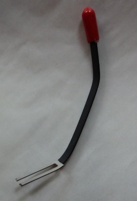
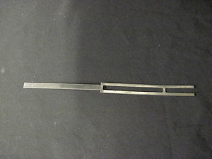
To make room for all the tape players, and to get rid of redundant features like AM/FM radio and alarm clock, I had to remove the doors that keep the tapes in position. I also did that on the original Melloman, but I was able to use rubber bands. Rubber bands don't look so nice, and that solution didn't really work on this machine, so I had to do something different. The solution was to use Yamaha key-springs (thanks for the idea and the key-springs, Russ). I cut the springs in half, carefully bent them by hand, covered them in heat shrink tubing, then glued a rubber thread cap to the tops. The solution works, but it is kind of a pain to remove the tapes.
The keyboard that's used to play notes (aka gate the tape tracks) is from a junked Casiotone. In order to make this work, I had to cut down the keybed from 49 or so keys to 25, C to C. The original key contact circuit board was used, but it also had to be cut. Next, the key routing needed to be "re-matrixed". For the keying to work, each note needs to switch to a common rail of 9v. This voltage is then routed to the opto-coupler circuit board to gate the notes. To rematrix, you just need an ohm meter, and you have to selectively short traces so that ultimately, one side of each switch goes to a common point. Then you solder the leads to the diodes. For this, the current doesn't really need to go through the diode since all the keys are now discrete switches. Though the voltage drop through the diodes would be small enough to still turn on the transistors on the keying circuit.
On the new Melloman, each keyed track is sent to an active mixing circuit. I used a TL072 opamp, and the final output is line level mono. Switching on the Speaker Switch routes the output through another amplifier stage to drive the two 4 ohm speakers wired in series (8 ohm amp).
A small panel on the back of the instrument contains a grounded IEC power socket, and 1/4" output jack.
The power comes from a switching supply that provides +/-12V and +5V from 120VAC. Those voltages are sent to regulators to provide +/-9V and +3v rails for the instrument.
Now please enjoy some pictures. There is a video clip at the bottom of the page, and a link with pictures I took building the New Melloman